Flashing custom firmware on a Gosund SP111
We have some older generation Teckin SP22’s which I previously flashed with Espurna. They have since changed the model making it harder to flash due to the removal of the 4 screws on the back. People online reported some levels of success using Tuya Convert, but I wanted something that I could flash via serial.
This lead me to looking into alternatives, eventually leading me to the Gosund SP111 due to it also featuring power reading capabilities and higher load rating.
Note Be sure to get the higher rated 3500W (15A) version as they container the newer PCB that provides such ease of flashing.
To flash this device, you will need:
There are several custom firmwares available for these ESP8266 based devices, including:
This time I went with Tasmota as it was well documented, has a big community, and I wanted to try something different.
Preparing the device
To be able to flash the device you must first remove a single philips head screw which can be done from the back of the device.
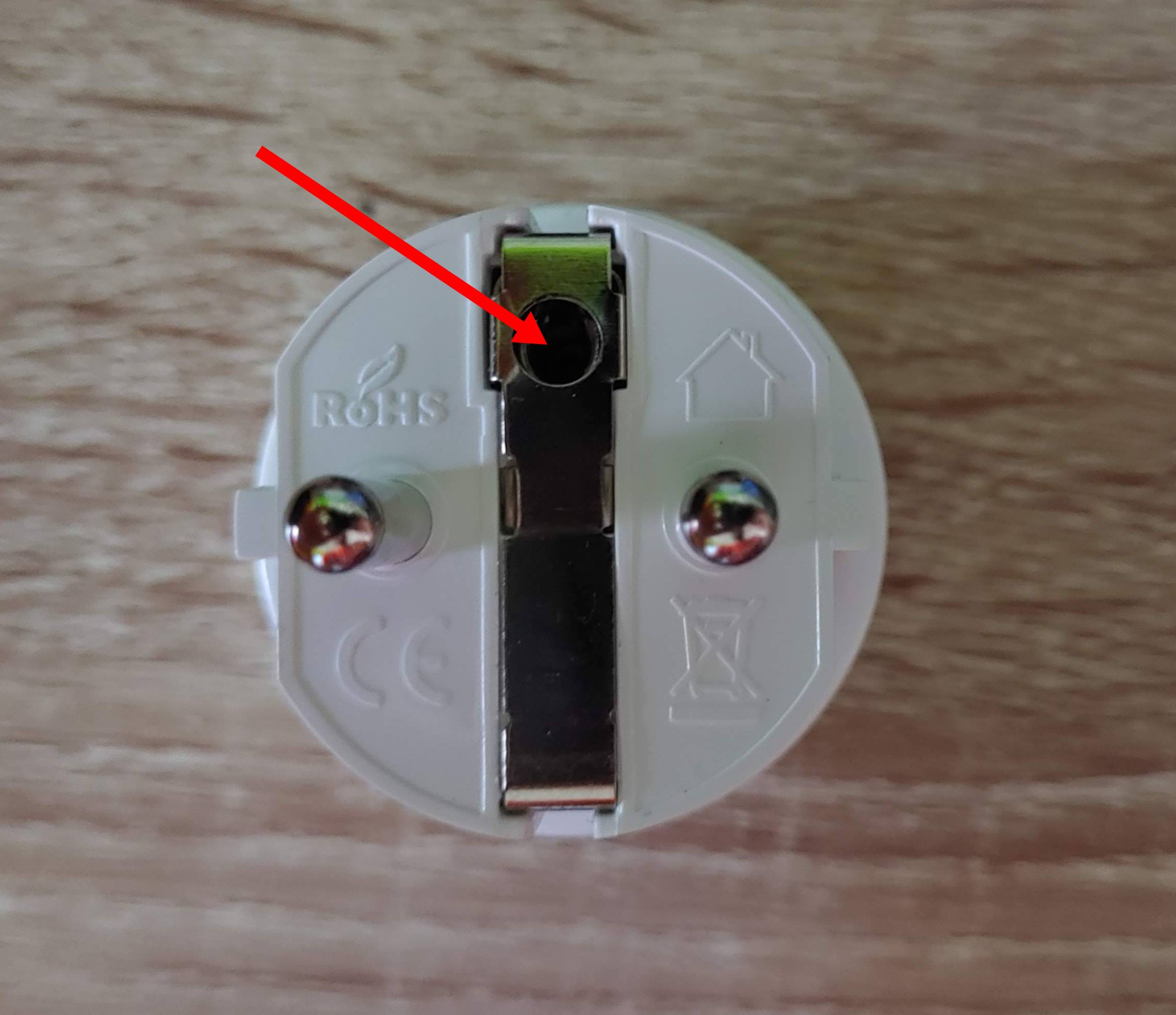
Once loosened you should be able pop off the top, around the translucent rim.
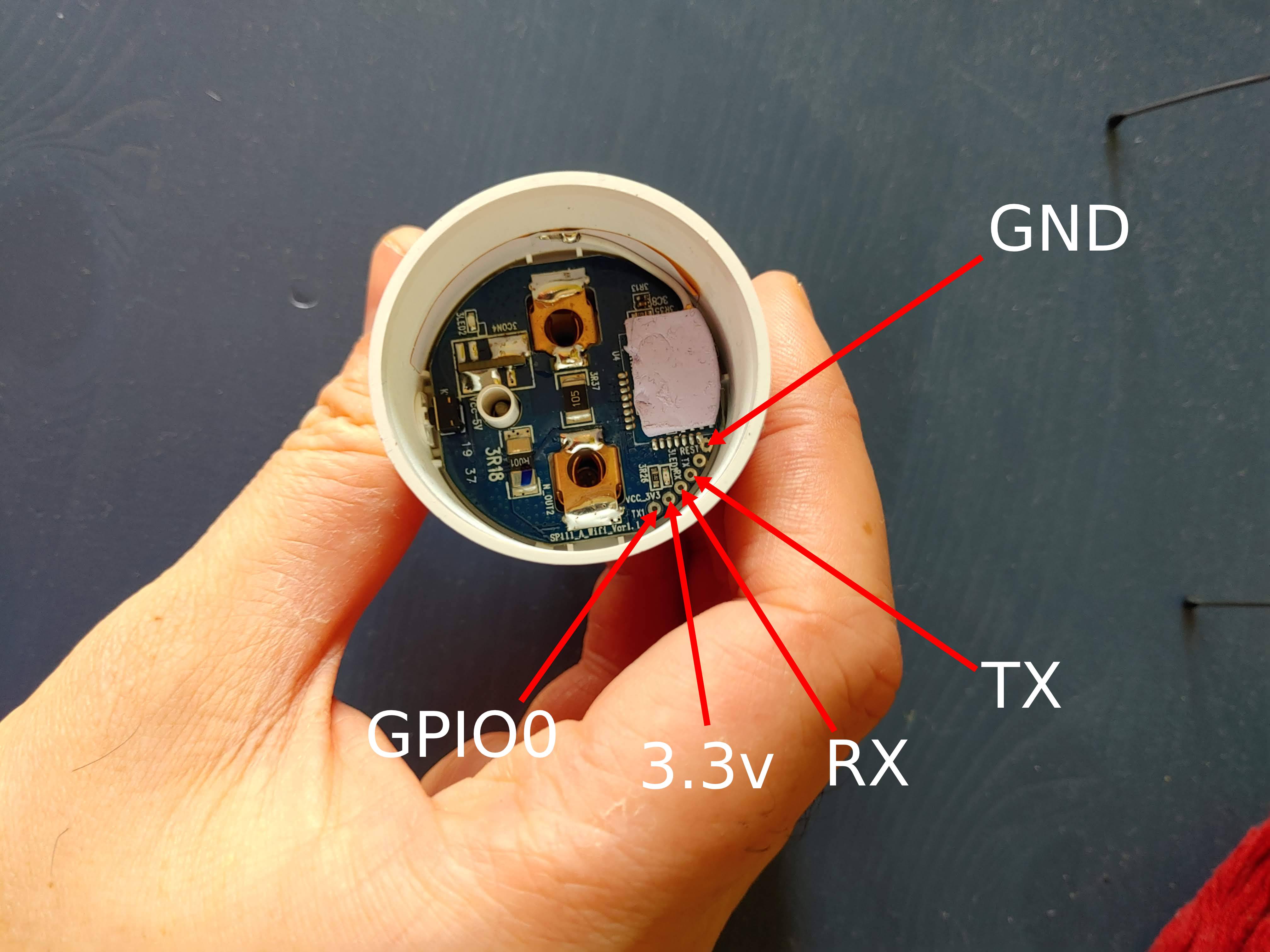
As you can see from the diagram there are the soldering points exposed which we must connect the relevant jumper cables too.
| FTDI | Gosund |
|---|---|
3.3v | 3.3v |
GND | GND |
RX | TX |
TX | RX |
This table outlines the way in which you should connect the plug to the FTDI adaptor.
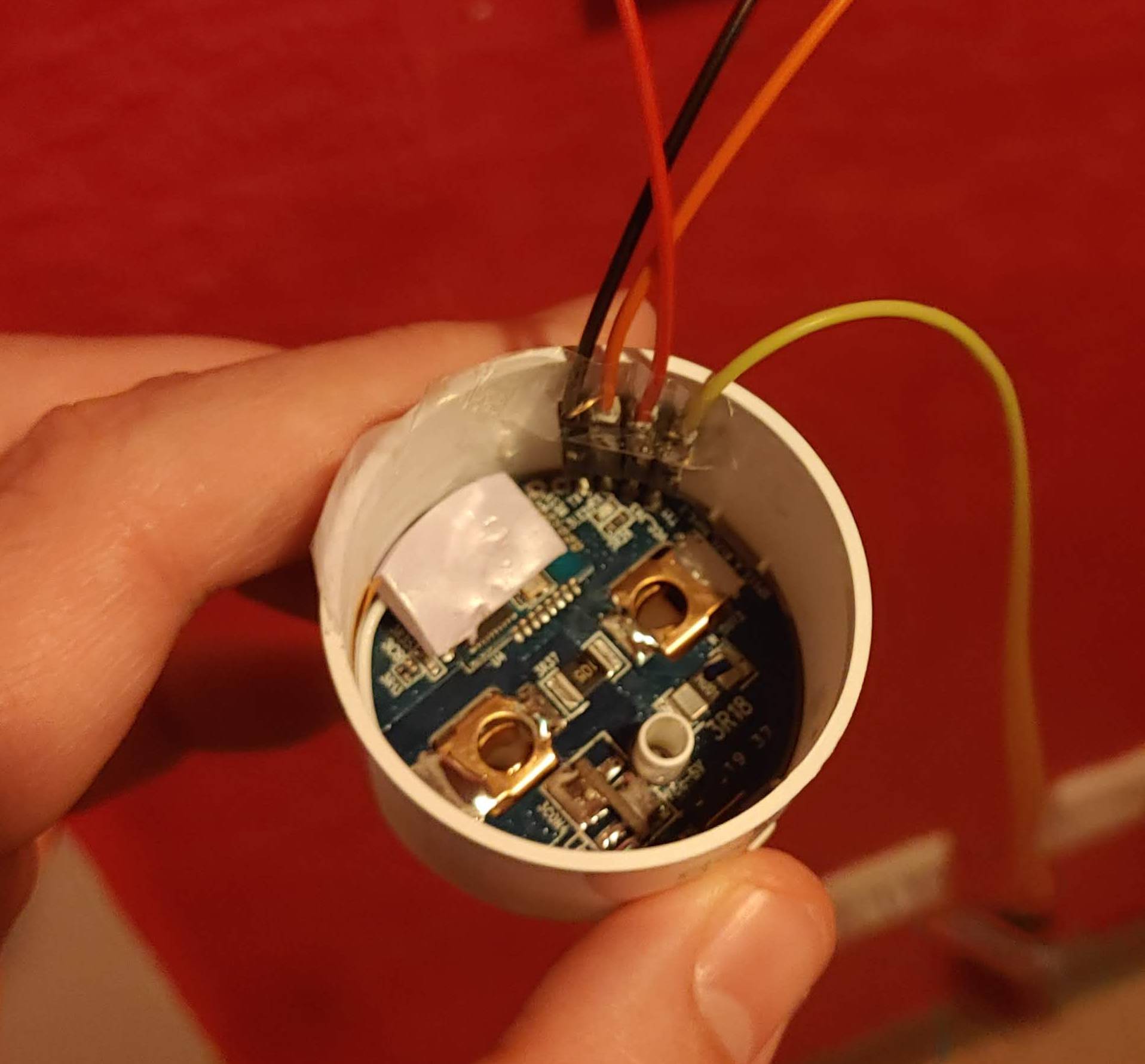
I ended up sharpening the male ends of the jumper cables slightly so that they would fall slightly through the holes, using tape to secure them to the side of the device making it easier to work with.
Note the diagram above is for illustration purposes and missing
GNDbeing connected.
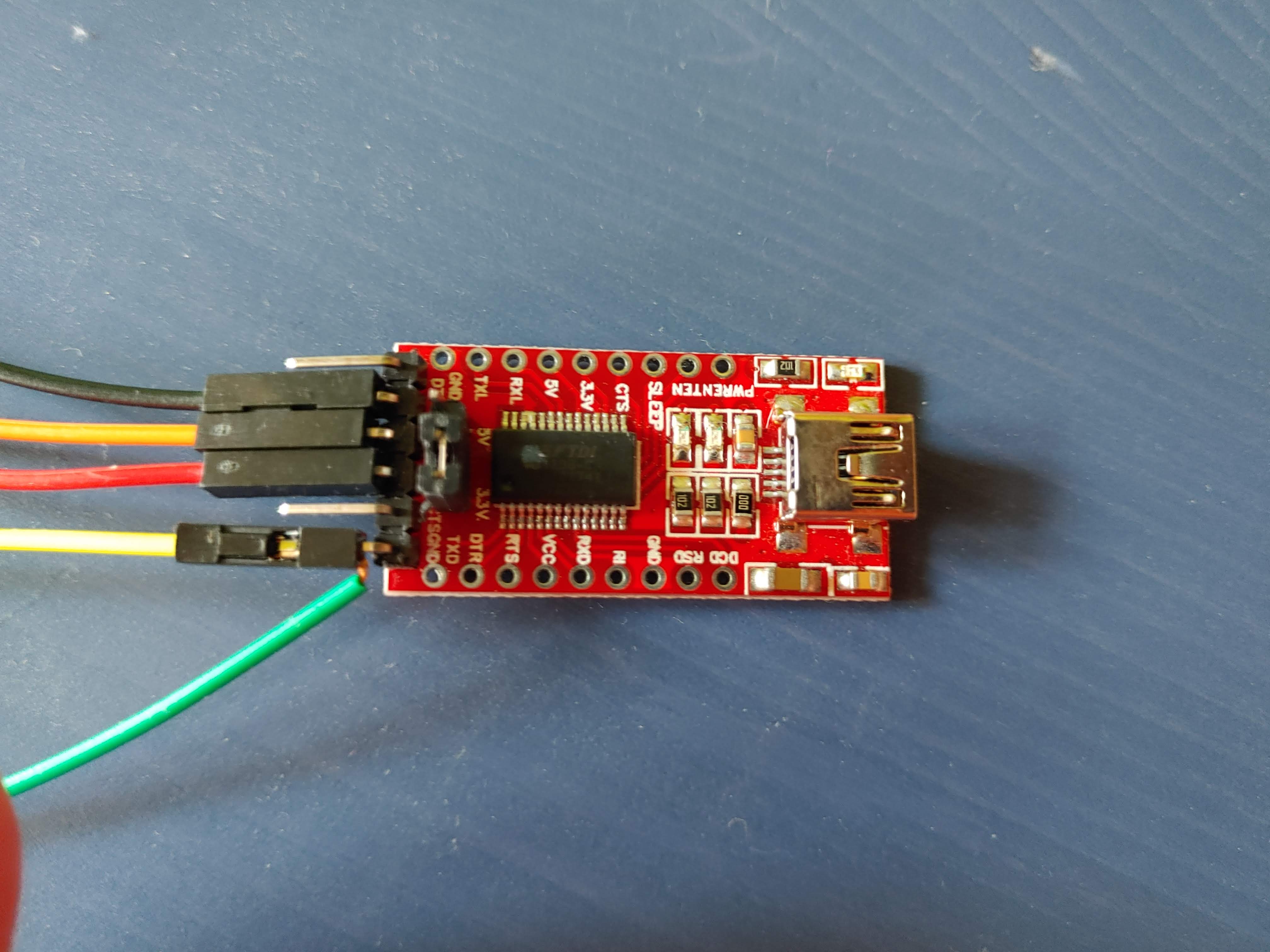
Here is the other end of the FTDI wired up showing the two cables wired to GND which will be used later for putting the device into flashing mode.
Flashing
For the flashing process I used esptool a simple well documented command line tool.
To put the device into flashing mode you need to cross GPIO0 with GND for a few seconds whilst connecting the FTDI adaptor.
You can easily do this by holding the bridged cable on GPI0 by hand and removing shortly after. To tell this worked correctly when removed the red LED turns dimmed, indicating it’s in flashing mode.
Backup existing firmware (optional):
sudo esptool.py --port /dev/ttyUSB0 read_flash 0x00000 0x100000 <name-of-backup>.bin
replacing <name-of-backup> with something more meaningful like gosund-sp111-v1.1
Erasing existing firmware:
sudo esptool.py --port /dev/ttyUSB0 erase_flash
Flashing new firmware
sudo esptool.py --port /dev/ttyUSB0 write_flash -fs 1MB -fm dout 0x0 sonoff.bin
where sonoff.bin is the latest Tasmota build.
Once finished, disconnect cables and assemble device. Follow the official documentation from here regarding setting up the device.
Template
Here is the device template that I used to configure the device:
{"NAME":"Gosund SP111 V","GPIO":[57,255,56,255,132,134,0,0,131,17,0,21,0],"FLAG":0,"BASE":45}